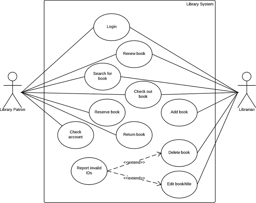

In the 1990s, there were several different ways to represent and document software systems. UML was created as a result of the chaos revolving around software development and documentation. By using visual representations, we are able to better understand possible flaws or errors in software or business processes.

As the old proverb says: “a picture is worth a thousand words”. It is based on diagrammatic representations of software components. In fact, it’s one of the most popular business process modeling techniques.

Simply put, UML is a modern approach to modeling and documenting software. UML is an acronym that stands for Unified Modeling Language. A UML diagram is a diagram based on the UML (Unified Modeling Language) with the purpose of visually representing a system along with its main actors, roles, actions, artifacts or classes, in order to better understand, alter, maintain, or document information about the system.


 0 kommentar(er)
